The Basic Gate design
|
Gate Installation Part 1 - September 2014 |
 |
Concrete Gate Piers
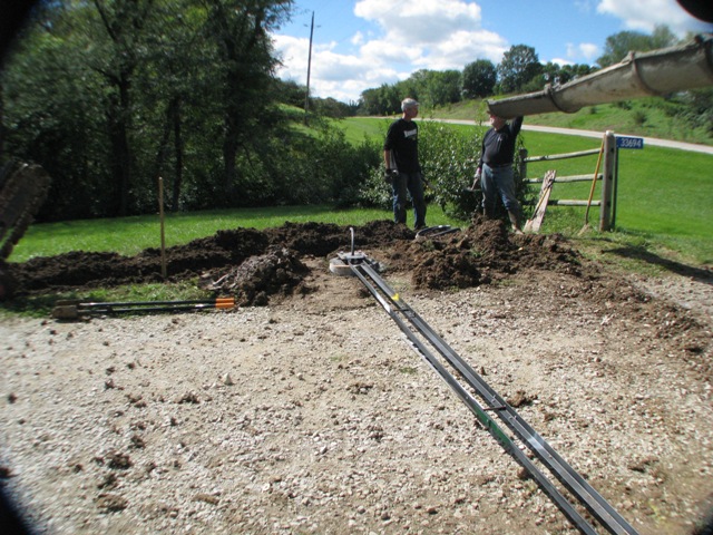
A special gate post positioning template has been used to correctly position the "J" bolts into each concrete pier. This assures that the gate posts are exactly positioned relative to the drive way. Taking some time with this step proves to be a real time saver during the gate installation! |
Photo1: Special gate post positioning template |
|
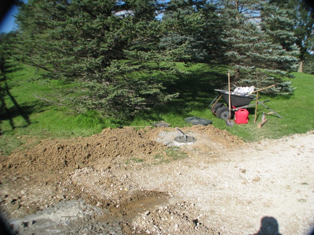
The North Gate Base is ready for installation
All trenching and flexible conduit is in place and concrete form has been poured. Trenches have been filled and tamped in place. |
 |
| |
Photo 2: North Gate Base |
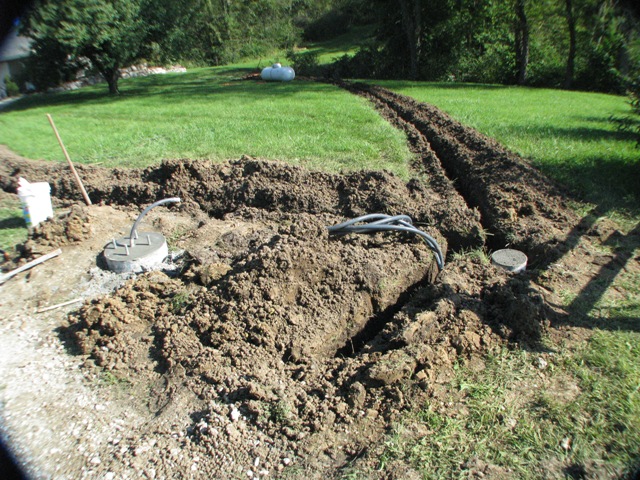 |
South Gate Base and controller base
This shows some of the additional trenching to support the gate exit sensor, to the left, and the main power trench toward the propane tank in the upper part of the picture. The controller base is to the right in the picture. |
Photo3: South Gate Base |
|
Gate Installation Part 2 - October 2014 |
|
|
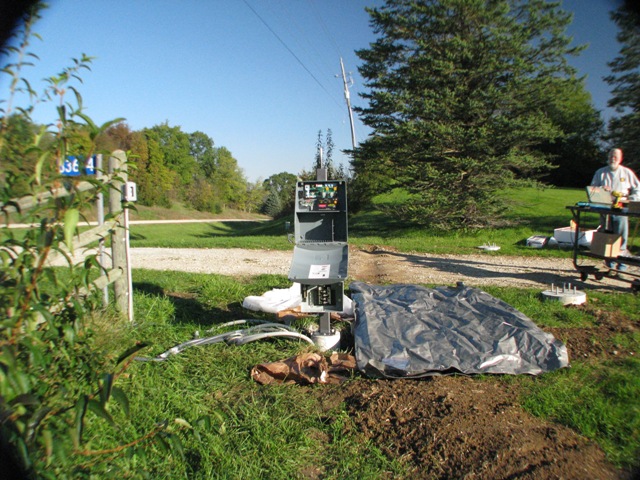
Control and Power Panel Installation
I decided to mount the power and controller on the same steel base unit. The Controller is powered completely by the Solar panel in photo 5. The LED lights on the main gate posts are powered by a 12 volt DC power supply and are controlled by a photo cell for dusk to morning operation. |
 |
| |
Photo 4: Controller and Power Panel |
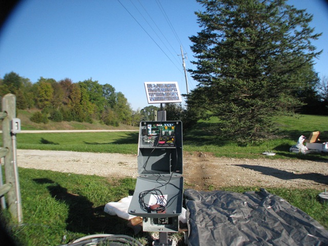 |
Solar Panel Installation
The solar panel attachment is designed to allow me to add sun following controllers later.
Note that eight feet long ground rods were installed at the control panel, at the end of the underground sensor, and at each gate post. |
Photo 5: Solar Panel and Controller |
|
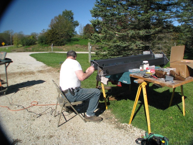
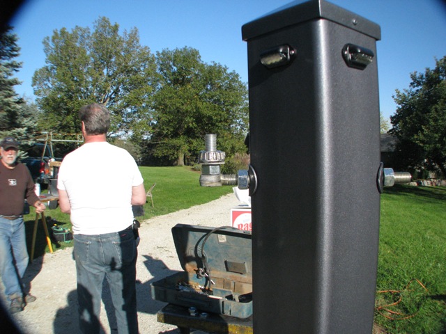
Gate Post Wiring
Each gate post is constructed from 6" X 6" Steel tubing to which a four-hole bolting pad has been welded. This allows for each post to be exactly aligned with the hanging gate panels, providing perfect final gate alignment. Each post is secured on the 18 inch concrete pier with four special J bolts almost three feet long. These bolts extend above the concrete piers to allow a nut and washer on the top and bottom of the post pad. The posts and the gates are primed with a special epoxy primer to protect the basic steel, and covered with two coats of special automotive gray paint with a small amount of metallic finish. |
 |
| |
Photo 6: Gate Post Wiring |
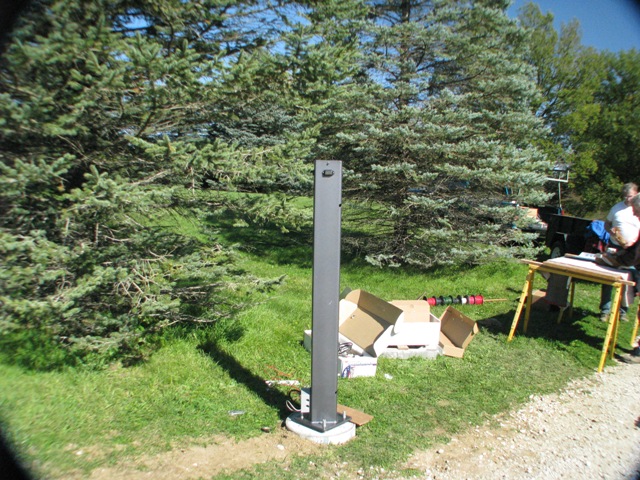 |
North Gate Post
The first Gate post has been installed! All the wiring easily slipped into the flexible PVC conduit. Two electrical circuits will be run from the control panel to each post. The first is the five-wire actuator cable that provides power to the each gate opener. The second circuit is a 12VDC source to the LED lamps at the top of each gate post. This circuit is not part of the solar powered gate system, but is a separate 12VDC source. |
Photo 7: North Gate Post |
|
Timken Roller Bearings
To minimize the force necessary to open and close each gate panel, Timken roller bearings were installed at each gate post. This photo shows a close up of the design. We estimated each gate panel to weigh about one hundred and twenty pounds, but you can open or close the gate with a small amount of pressure from your little finger! Sure there is still a static mass to overcome, but it really does operate easily! |
 |
|
Photo 8: Timken Roller Bearings |
 |
South Gate Wiring
Judd and Clete are pulling the final set of wires to the south Gate concrete pad. The actual run is about 12 feet of wire up to the control panel. |
Photo 9: South Gate Wiring |
|
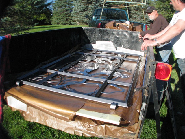
Unloading the Gate Panels
At last! The fun begins! The panels arrived on site with no scratches or problems. The task will be to unload them with creating the first scratch. Because they are separated with a layer of waxed paper, the unloading proves to be no problem. Yay! |
 |
| |
Photo 10: Unloading the Gate Panels |
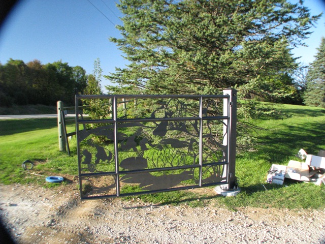 |
North Gate Panel is Installed!
The gate installation proved to be very easy. Each gate bearing assembly provided maximum adjustment. Because this was the first gate to by hung, we made sure to keep the swing short so it would not hit the south gate when it was installed next. |
Photo 11: North Gate Panel is Installed! |
|
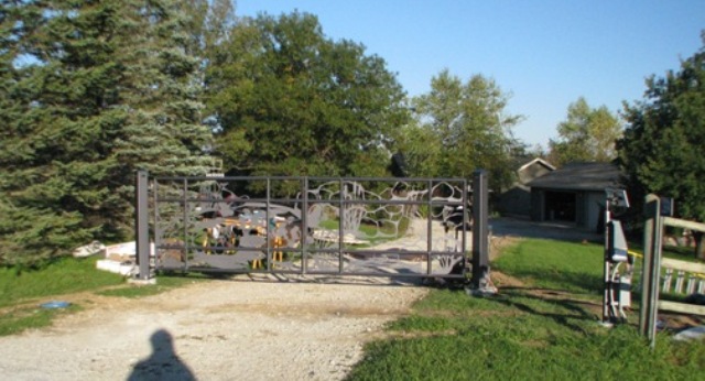
The Gate is Installed!
Final gate panel installation proved to be easy. The firststep was to ensure that each gate post was perfectly plumb. Then we brought the two gate panels carefully together and adjusted the gap between the panels. Each panel was finally leveled and rechecked for all clearances. The electrical cables were connected to each gate actuator and the actuators were tested for open and close operation. Finally, we set the actuators to the open position and attached each gate panel to the actuator. The actuators were unplugged from the control board, and each actuator was plugged in singly, and tested for proper open/close operation. At last, both actuators were connected and a gate open/close operation was tested. It worked like a charm! A car was used to test buried gate opener, because it was buried at two feet. We found that it was actually sensitive enough at that depth to be triggered with a large metal snow shovel. I had hoped to make it much less sensitive by burying the sensor at two feet! Oh, well! |
 |
| |
Photo 12: The Gate |